DJI Zenmuse H3-3D – repair (Part 1?)
Big Drama…
I had a pretty horrible crash with my DJI F550. There was a catastrophic resonance which made the copter unstable and uncotrollable. The  Drama was, that my beloved DJI Zenmuse H3-3H Gimbal was underneath, when it crashed on the roof. This is how the gimbal looked… (Thank god, the GoPro was OK)
The first problem was a sticking ‘roll’-axis. It was easily fixable. The axis of the roll axis has an easily reachable screw which claps the motor to the axis. The arm squeesed onto the regulator PCB due to the crash. Fixing was as easy as loosening the screw and tightening it again.
 But, at a close look, I found a defect halleffect sensor on the ‘nick’-motor of my gimbal. Normally this is a death-sentence.
 Googling A search online yielded that the DJI motors are sold and made nowhere. Not even Alibaba.
After I tore down the gimbal and removed the motor, halleffect sensor crumbs fell out of it. The other sensor were labelled ‘1432’, which yielded exactly no results, aside from some analog Sensors from Allegro. Important to note was that Pins 1 and 3 of the 3 remaining sensors were connected to each other. Also, Pin 2 of these SOT23 sensors were connected to something what seemed to be a ground pour. Some cross-referencing later it turned out that the pinout 1: VCC, 2: OUT, 3: GND i a pretty usual pinout for halleffect sensors in SOT23 package. Conveniently, there also was a small ceramic cap on the flex-PCB which was connected to Pins 3 and 1 respectively GND and VCC. I traced one of the remaining sensor outputs to the flex-connector, where I removed the kapton and connected a wire (please re-check the pinout on the picture). I set a current limit of 5mA and slowly raised the voltage to 4.5V. But, unfortunately, there was no recation to stimulation with a neodymium magnet. It was not before i connected my scope and found some interesting spikes. The sensors on the motor have open-drain outputs.
But which kind of halleffect sensors are they?
There are several types of hall effect sensor. Bipolar, unipolar, latching, analog, … luckily, there are very nice videos on Micronas’ Youtube Channel – [1] [2], which neatly explain the behavior of bi- and unipolar hall effect sensors. In our case, the output of the sensors was consistent with unipolar halleffect sensors. Quickly checking out Farnell I found  the SS360xT (x for North or South) from Honeywell as up to the job. The only thing still unknown was the polarity of the sensor (north-on or south-on). So I ordered both categories…
After testing which polarity was the right one (magnets!) (NORTH in our case – so it’s SS360NT) I mounted the sensor in the motor, 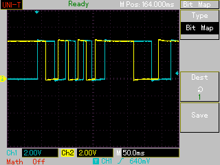 which was not quite easy duue to some kind of melting plastic, and attached a wire to it’s output in the usual way.
I mounted ‘freestyle’ pullups for open-drainability and hooked everything up for a test….
Actually looks pretty nice. Yelloow is our new sensor. Interestingly, our new sensor seems to be ‘high’ on power-on, which the others aren’t.
Apart from that the sign al looks as we would imagine such a signal, showing magnet position in a imaginary circle, measuring always 120° apart.
Now of course it is on to putting it all back together. It’s important to note that the notch in the little gear which turns the pot on the controller PCB must  be aligned with the notch on the motor axle. Otherwise, the closed-loop-control isn’t working right. Apart from that, always align the screws with the notches in the axles…
Tada – The gimbal is working again! 🙂
The (absolute) angle of the ‘roll’ axis is still off because it’s mount is bent. But that maybe is

part of part 2… 🙂


I have a P2 with a DJI Zenmuse H3-3D, I need motor control board YAW Driver V1
Hi I think buying a defective gimbal from ebay should work. Or you can always try DJI…
I have a P2 with a DJI Zenmuse H3-3D but it seems one of the ports on the motor control board where the ribbon cable attaches has come off the board do you know a place where I can get a replacement board?
No. It is a ca 15mm long piece of machined metal witz a set screw in it. The plastic piece in the image is just a press fit piece for turning the position feedback pot on the PCB.
Is this image you posted, the adapter you mean? http://www.tobias-schlegel.de/wp-content/uploads/2015/03/image011.jpg, the h43d dont seem to have that….
Hi,
I’m sorry but no. The Bells are fixed to the axles, most likely by shrinking them onto the axles and or by crimping.
The only thing you can do is to remove the bells and the axles as complete assembly, by losening the
setscrew on the axle adapters. You can then push the axles through the Stators and thus remove the assembly.
Good luck!
Hi,I’m having a hard time removing the motor bells. I’m using the h43d but it looks very similar to your h33d. Do you have detail pics how u removed the bells please?
Thanks!
It’s quite easy, as soon as you remove the hardware attached to the motors (small hex screws) you can remove the magnetic bell…
nice post, one question, how do u manage to open the motors?